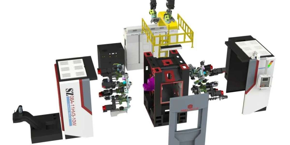
The integrated transfer machine can greatly save the floor area of the machine tool. By changing the feed direction from horizontal or inclined to top-down feed, the guide rail can be placed above the workpiece behind, reducing the distance between the workpiece and the operator, facilitating the observation of the turning state of the workpiece, and facilitating the operator to load and unload. The determination of coordinate axes, generally determine the Z axis, X axis, Y axis, and finally determine other axes.
(1)Z axis: The direction of Z axis is determined by the main axis of the cutting force transmitted by the main axis, and the coordinate axis parallel to the main axis is the Z axis. As shown in the figure. If the machine has no spindle, the Z-axis is perpendicular to the workpiece loading surface. At the same time, the direction of the tool away from the workpiece is the positive direction of the Z axis.
(2)X axis: The X axis is parallel to the loading surface of the workpiece and perpendicular to the Z axis. This is the main coordinate of the motion in the positioning plane of the tool or workpiece. For a machine with a rotating workpiece, the X-coordinate is in the radial direction of the workpiece and parallel to the transverse slide. The direction of the tool away from the center of rotation of the workpiece is the positive X axis. For a rotating tool, if the Z axis is vertical, the X direction is moving to the right. If the Z-axis is horizontal, the main axis is to the right and viewed from the main axis towards the workpiece.
(3)Y axis: Y axis perpendicular to X and Z axis. According to the positive direction of X and Z coordinates, the positive direction of y motion is determined according to the right-handed Cartesian coordinate system.
(4) Rotational motion: respectively using A,B,C to represent the rotation around the axis X, Y,Z. Their positive orientation is determined by the right hand spiral rule.
(5) Additional axes: In addition to X, Y and Z coordinates, there are coordinates parallel to them, which can be represented by P,Q and R, respectively.
(6) The workpiece movement in the opposite direction: when the machine tool movement is not the machine tool movement, the tool movement must be arranged in accordance with the above provisions. Use the letter "'", such as +Y ", to indicate the workpiece's forward motion with respect to the tool. If there is no "'", such as +Y, it represents the negative motion of the tool relative to the workpiece.
integrated transfer machine https://www.zjshuangzheng.com/Integrated-Transfer-Machine.html


